
ePMDuct User Guide
Installation, wiring and Modbus RTU integration guide for the ePMDuct in-duct particulate monitoring probe.
Version 1.3
1. Versionning#
| Version | Date | Author | Updates |
|---|---|---|---|
| V0 | 31/07/2025 | Grégoire Janin / Thibaud Guillien / Thomas Thouvenin | Creation / Draft Version (modbus table / hardware / error code / mechanical …) |
| V1 | 22/12/2025 | Vincent Bartolomei | First Official version (polished) |
| V1.2 | 20/02/2026 | Vincent Bartolomei | Updated version with implementation of mechanical mounting part, caution warranty and exception part, maintenance part |
| V1.3 | 24/02/2026 | Antoine Dumas | Verification |
2. Caution and warranty exceptions#
This product is not intended for use by children or disabled person, only by qualified personnel ;
- Do not use near a heat / flammable source ;
- Do not immerse the product in liquid ;
- Do not hit or damage your device ;
- Do not disassemble the product (unless otherwise specified in the manual) ;
- Do not insert foreign bodies into the holes ;
- Do not use tools to disassemble the product (unless otherwise specified in the manual) ;
- Carry out maintenance of the product (cleaning the product and replace sensor NextPM Advanced + pump when recommended)
Damages not covered by standard warranty:
- Damages caused by an improper use of the product such as shocks, drops, exposition to extreme temperatures, dust, or humidity, or any other cause.
- Damages resulting from any non-respect of manufacturer instructions.
- Cosmetic damages such as scratches, paint, glue or any other alteration made to the product.
- Damages to the product after a repair or disassembly from non authorized personnel.
This product is covered by a 1-year product warranty which is valid from the date of delivery. Users are not permitted to make changes or modify the device in any way. Changes or modifications not expressly approved by the party responsible for compliance will void the user’s warranty.
European Union Directives Conformance Statement#
Hereby, Tera Sensor declares that this product is in compliance with:
- All relevant EU Directives
You can view your product’s Declaration of Conformity (DoC) at www.tera-sensor.com
Caring for the environment by recycling#
Do not dispose of electrical devices or accessories with your household waste.
In some countries or regions, collection systems are set up to handle electrical and electronic waste items. Contact your regional authorities for more details.
3. System description#
3.1 About ePMDuct#
The ePMDuct is an advanced air quality measurement instrument designed for real-time monitoring of particulate matter (PM) within ventilation ducts. Integrating the high-precision NextPM Advanced sensor, it provides reliable data on particle concentrations. This guide is intended to assist technical staff in the mechanical installation, wiring, and software integration of the device via the Modbus RTU protocol.
It is possible to measure particles classified in 5 different channels:
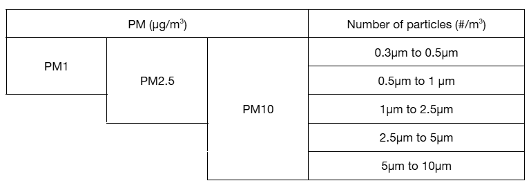
Here below an overview of the product:
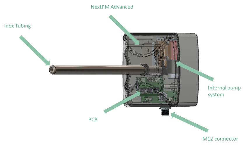
Figure 1: General description of the ePMDuct
Pinout and electrical considerations#
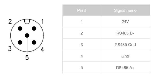
- The ePMDuct must be power supplied with + 24 VDC / 0.5V.
- The device has a nominal power consumption of 2.9 W. Under peak load (pump at maximum PWM), power consumption may reach 5.5 W. In standby mode (measurements disabled), consumption drops to less than 0.1 W.
- The M12 connector can be purchased to connect the ePMDuct. Those connectors are IP67.
To connect the ePMDuct to a PLC/Gateway, it is either possible to link it directly or to use a ModeLinkChainer (Tera Analytics device description here).
3.3 Generals#
- Product specifications, such as range, precision, conditions of use, etc.., are defined into the datasheet of the ePMDuct which can be found at https://tera-sensor.com/
- The user can find explanations about fluidic and mechanics to be helped for its ePMDuct use/integration by referring to the ePMDuct integration advice chapter.
3.4 Package content description#
Before starting the installation, please ensure that all the following items are present in the package. If any component is missing or damaged, please contact Tera Sensor support.
The standard ePMDuct package includes:
- 1 x ePMDuct Device: Pre-assembled with its industrial housing, internal PCB and pump + sensor NextPM Advanced, and the inox probe (with the selected size of 20 cm or 40 cm, to ask at quotation stage).
- 1 x Male Mounting Plate: Pre- mounted on the ePMDuct.
- 1 x Female Mounting Plate: To fix on the duct with 4 screws of 3.9 x 35 mm (screws not included).
- 1 x Foam gasket: To ensure airtight sealing between the probe and the duct.
4. Communication protocol Modbus RTU#
4.1 Read Discrete Inputs (0x03)#
| Registers | Name | Description |
| 01 (0x01) | ePMDuct Firmware | Firmware number ePMDuct |
| 02 (0x02) | Timestamp ePMDuct | Time on (min) Reset each time tuned off/on |
| 03 (0x03) | Status Error ePMDuct | ePMDuct error code |
| 18 (0x12) | NextPM Adv Firmware | Firmware number NextPM Adv |
| 19 (0x13) | Status Error NextPM Adv | NextPM Adv error code |
| 20-21 (0x14 - 0x15) | Number of 0.3µm to 0.5µm on 10 sec | Number of particles from 0.3µm to 0.5µm (Nb/L) with running average on 10 sec |
| 22-23 (0x16 - 0x17) | Number of 0.5µm to 1µm on 10 sec | Number of particles from 0.5µm to 1µm (Nb/L) with running average on 10 sec |
| 24-25 (0x18 - 0x19) | Number of 1µm to 2.5µm on 10 sec | Number of particles from 1µm to 2.5µm (Nb/L) with running average on 10 sec |
| 26-27 (0x1A - 0x1B) | Number of 2.5µm to 5µm on 10 sec | Number of particles from 2.5µm to 5µm (Nb/L) with running average on 10 sec |
| 28-29 (0x1C - 0x1D) | Number of 5µm to 10µm on 10 sec | Number of particles from 5µm to 10µm (Nb/L) with running average on 10 sec |
| 30-31 (0x1E - 0x1F) | Number of 0.3µm to 0.5µm on 1 min | Number of particles from 0.3µm to 0.5µm (Nb/L) with running average on 1 min |
| 32-33 (0x20 - 0x21) | Number of 0.5µm to 1µm on 1 min | Number of particles from 0.5µm to 1µm (Nb/L) with running average on 1 min |
| 34-35 (0x22 - 0x23) | Number of 1µm to 2.5µm on 1 min | Number of particles from 1µm to 2.5µm (Nb/L) with running average on 1 min |
| 36-37 (0x24 - 0x25) | Number of 2.5µm to 5µm on 1 min | Number of particles from 2.5µm to 5µm (Nb/L) with running average on 1 min |
| 38-39 (0x26 - 0x27) | Number of 5µm to 10µm on 1 min | Number of particles from 5µm to 10µm (Nb/L) with running average on 1 min |
| 40-41 (0x28 - 0x29) | Number of 0.3µm to 0.5µm on 15 min | Number of particles from 0.3µm to 0.5µm (Nb/L) with running average on 15 min |
| 42-43 (0x2A - 0x2B) | Number of 0.5µm to 1µm on 15 min | Number of particles from 0.5µm to 1µm (Nb/L) with running average on 15 min |
| 44-45 (0x2C - 0x2D) | Number of 1µm to 2.5µm on 15 min | Number of particles from 1µm to 2.5µm (Nb/L) with running average on 15 min |
| 46-47 (0x2E - 0x2F) | Number of 2.5µm to 5µm on 15 min | Number of particles from 2.5µm to 5µm (Nb/L) with running average on 15 min |
| 48-49 (0x30 - 0x31) | Number of 5µm to 10µm on 15 min | Number of particles from 5µm to 10µm (Nb/L) with running average on 15 min |
| 50-51 (0x32 - 0x33) | PM₁ 10 sec average (Nb/L) | average over 10s of particles quantity per liter whose size is < 1μm |
| 52-53 (0x34 - 0x35) | PM₂.₅ 10 sec average (Nb/L) | average over 10s of particles quantity per liter whose size is < 2.5μm |
| 54-55 (0x36 - 0x37) | PM₁₀ 10 sec average (Nb/L) | average over 10s of particles quantity per liter whose size is < 10μm |
| 56-57 (0x38 - 0x39) | PM₁ 10 sec average (µg/m³) | average over 10s of particles mass concentration (µg/m³) whose size is < 1μm¹ |
| 58-59 (0x3A - 0x3B) | PM₂.₅ 10 sec average (µg/m³) | average over 10s of particles mass concentration (µg/m³) whose size is < 2.5μm¹ |
| 60-61 (0x3C - 0x3D) | PM₁₀ 10 sec average (µg/m³) | average over 10s of particles mass concentration (µg/m³) whose size is < 10μm¹ |
| 62-63 (0x3E - 0x3F) | PM₁ 1 min average (Nb/L) | average over 1 min of particles quantity per liter whose size is < 1μm |
| 64-65 (0x40 - 0x41) | PM₂.₅ 1 min average (Nb/L) | average over 1 min of particles quantity per liter whose size is < 2.5μm |
| 66-67 (0x42 - 0x43) | PM₁₀ 1 min average (Nb/L) | average over 1 min of particles quantity per liter whose size is < 10μm |
| 68-69 (0x44 - 0x45) | PM₁ 1 min average (µg/m³) | average over 1 min of particles mass concentration (µg/m³) whose size is < 1μm¹ |
| 70-71 (0x46 - 0x47) | PM₂.₅ 1 min average (µg/m³) | average over 1 min of particles mass concentration (µg/m³) whose size is < 2.5μm¹ |
| 72-73 (0x48 - 0x49) | PM₁₀ 1 min average (µg/m³) | average over 1 min of particles mass concentration (µg/m³) whose size is < 10μm¹ |
| 74-75 (0x4A - 0x4B) | PM₁ 15 min average (Nb/L) | average over 15 min of particles quantity per liter whose size is < 1μm |
| 76-77 (0x4C - 0x4D) | PM₂.₅ 15 min average (Nb/L) | average over 15 min of particles quantity per liter whose size is < 2.5μm |
| 78-79 (0x4E - 0x4F) | PM₁₀ 15 min average (Nb/L) | average over 15 min of particles quantity per liter whose size is < 10μm |
| 80-81 (0x50 - 0x51) | PM₁ 15 min average (µg/m³) | average over 15 min of particles mass concentration (µg/m³) whose size is < 1μm¹ |
| 82-83 (0x52 - 0x53) | PM₂.₅ 15 min average (µg/m³) | average over 15 min of particles mass concentration (µg/m³) whose size is < 2.5μm¹ |
| 84-85 (0x54 - 0x55) | PM₁₀ 15 min average (µg/m³) | average over 15 min of particles mass concentration (µg/m³) whose size is < 10μm¹ |
| 106 (0x6A) | Relative humidity (internal) | Relative humidity in % (to be multiplied by 100) |
| 107 (0x6B) | Temperature (internal) | Temperature in °C (to be multiplied by 100) |
| 199 (0xC7) | Sleep mode | Sleep mode (0 ePMDuct awake, 1 ePMDuct sleeping) |
| 200 (0xC8) | Measuring period | Measuring time with the NextPM (in sec) by cycles of 15 minutes. Cycle time cannot be modified |
| 201-202 (0xC9-0xCA) | Total time ON (Sec) | Total functioning time of the sensor and the pump in the device² |
¹ Mass concentration should be divided by 1000 to get the value in µg/m³.
² Value reset automatically when a new sensor NextPM is replaced inside the ePMDuct.
4.2 Measurement decoding example#
Frame reading for registers 20-21 (0x14-0x15):
0x01 0x03 0x00 0x14 0x00 0x02 0x84 0x0F
ePMDuct answer:
0x01 0x03 0x04 0x02 0x3E 0x00 0x05 0x5A 0x44
Registers reading sequence:
0x02 0x3E: LSB
0x00 0x05: MSB
The final value (in Hex): 0x00 0x05 0x02 0x3E
Conversion in decimal: 328 254 (Number of particles per liter of air with a diameter between 0.3 et 0.5 µm)
4.3 Modbus write command (0x10)#
| 199 (0xC7) | Sleep mode function | Register to control sleep mode of the ePMDuct (description below) |
|---|---|---|
| 200 (0xC8) | Measuring period | Measuring time with the NextPM (in sec) by cycles of 15 minutes. Cycle time cannot be modified |
Writing command for register 199:
Sleep mode command is 0x01
Wake up command is 0x00
Any other command will not be considered.
Writing command for register 200:
The target value must be between 90 and 900 (seconds), representing a cycle duration of 1 minute 30 seconds to 15 minutes. Values outside this range will not be acknowledged by the ePMDuct.
Write frame example: 0x01 0x10 0x00 0xC8 0x00 0x01 0x02 0x00 0x84 0xB6 0x7B Where 0x00 0x84 represents 180, for 180 seconds of NextPM measurement.
This value is stored in flash memory; therefore, avoid writing this value repeatedly to prevent compromising flash integrity. The value is saved and retrieved upon ePMDuct startup (it remains in flash memory even in the event of a power failure).
4.4 Communication parameters#
Communication parameters (baud rate, address, parity, stop) can be modified directly via the switches on the instrument’s electronic board. The low and high states are indicated directly on each switch.
The PCB is represented below.
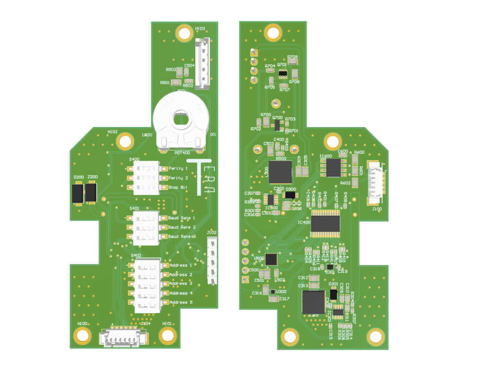
Figure 2: PCB description, left side for top face, right side for bottom face.
Baud rate#
| 3-Way Switch | |||
|---|---|---|---|
| Baud rate | Baud rate 3 | Baud rate 2 | Baud rate 1 |
| 1200 | 0 | 0 | 0 |
| 2400 | 0 | 0 | 1 |
| 4800 | 0 | 1 | 0 |
| 9600 | 0 | 1 | 1 |
| 19200 | 1 | 0 | 0 |
| 38400 | 1 | 0 | 1 |
| 57600 | 1 | 1 | 0 |
| 115200 | 1 | 1 | 1 |
Parity#
| 3-Way Switch - position 1 and 2 | ||
|---|---|---|
| Parity | Parity 2 | Parity 1 |
| none | 0 | 0 |
| Even | 1 | 0 |
| Odd | 0 | 1 |
Stop#
| 3-Way Switch - position 3 | |
|---|---|
| Stop | Stop Bit |
| 1 bit | 0 |
| 2 bits | 1 |
Modbus Address#
| 5-Way Switch | |||||
|---|---|---|---|---|---|
| Modbus Address | Address 5 | Address 4 | Address 3 | Address 2 | Address 1 |
| 0 | 0 | 0 | 0 | 0 | 0 |
| 1 | 0 | 0 | 0 | 0 | 1 |
| 2 | 0 | 0 | 0 | 1 | 0 |
| 3 | 0 | 0 | 0 | 1 | 1 |
| 4 | 0 | 0 | 1 | 0 | 0 |
| 5 | 0 | 0 | 1 | 0 | 1 |
| 6 | 0 | 0 | 1 | 1 | 0 |
| 7 | 0 | 0 | 1 | 1 | 1 |
| 8 | 0 | 1 | 0 | 0 | 0 |
| 9 | 0 | 1 | 0 | 0 | 1 |
| 10 | 0 | 1 | 0 | 1 | 0 |
| 11 | 0 | 1 | 0 | 1 | 1 |
| 12 | 0 | 1 | 1 | 0 | 0 |
| 13 | 0 | 1 | 1 | 0 | 1 |
| 14 | 0 | 1 | 1 | 1 | 0 |
| 15 | 0 | 1 | 1 | 1 | 1 |
| 16 | 1 | 0 | 0 | 0 | 0 |
| 17 | 1 | 0 | 0 | 0 | 1 |
| 18 | 1 | 0 | 0 | 1 | 0 |
| 19 | 1 | 0 | 0 | 1 | 1 |
| 20 | 1 | 0 | 1 | 0 | 0 |
| 21 | 1 | 0 | 1 | 0 | 1 |
| 22 | 1 | 0 | 1 | 1 | 0 |
| 23 | 1 | 0 | 1 | 1 | 1 |
| 24 | 1 | 1 | 0 | 0 | 0 |
| 25 | 1 | 1 | 0 | 0 | 1 |
| 26 | 1 | 1 | 0 | 1 | 0 |
| 27 | 1 | 1 | 0 | 1 | 1 |
| 28 | 1 | 1 | 1 | 0 | 0 |
| 29 | 1 | 1 | 1 | 0 | 1 |
| 30 | 1 | 1 | 1 | 1 | 0 |
| 31 | 1 | 1 | 1 | 1 | 1 |
4.5 NextPM Error Code Description#
The NextPM performs continuous internal diagnostics to keep the user informed of the sensor’s status and the validity of the measurements. The status is encoded on 2 bytes and contains flags corresponding to potential errors:
| Bit 15 | Bit 14 | Bit 13 | Bit 12 | Bit 11 | Bit 10 | Bit 9 | Bit 8 |
|---|---|---|---|---|---|---|---|
| - | - | - | - | - | - | - | - |
| Bit 7 | Bit 6 | Bit 5 | Bit 4 | Bit 3 | Bit 2 | Bit 1 | Bit 0 |
|---|---|---|---|---|---|---|---|
| Laser Error | Memory Error | - | T/RH Error | Heat Error | Not Ready | Degraded State | - |
Bit 1 (Degraded State): Set whenever a minor error is detected. In this state, the NextPM can still measure particles, but measurement quality is not guaranteed.
Minor errors include:
- Bit 3 (Heat Error): NextPM relative humidity remains above 60% for a period of 10 minutes.
- Bit 4 (T/RH Error): The measurement range is out of specification.
- Bit 6 (Memory Error): The sensor cannot access its memory; some internal smart functions will be unavailable.
- Bit 7 (Laser Error): The photodetector detects no particles for at least 240 seconds, indicating a possible laser error.
Bit 2 (Not Ready): Activated upon power-up or when waking from sleep mode. This indicates the sensor is starting up and measurements are unreliable until the bit is deactivated (duration: approx. 15 seconds).
4.6 ePMDuct Error Code Description#
| Bit 7 | Bit 6 | Bit 5 | Bit 4 | Bit 3 | Bit 2 | Bit 1 | Bit 0 |
|---|---|---|---|---|---|---|---|
| - | - | - | - | - | - | Etat statut NextPM | Communication state |
Bit 0 (Communication State):
- If 0: No communication issues.
- If 1: Communication error with the NextPM.
Bit 1 (NextPM Status):
- If non-zero, the NextPM error code is non-zero (presence of a sensor-level error).
5. Mechanical integration#
The ePMDuct is mounted onto a Duct using its quarter-turn fixing plate. The male part of the plate is already screwed onto the ePMDuct. The female part is screwed onto the Duct. The two parts are then locked together with a quarter-turn mechanism.
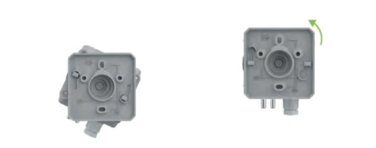
Figure 3: Mounting description of the ePMDuct
The orientation of the NextPM sensor is important; therefore, the ePMDuct must be installed according to the following instructions: The M12 connector must point towards the ground (see diagram below).
Be careful, depending on the duct diameter, you have the possibility to select between 2 probes sizes of 20 or 40 cm length. Note that the sampling recommendation is to place the probe end the closest possible to the duct center (a tolerance of 20 % can be acceptable). So the probe end has to be placed at min 30% length of the tube from the sides.
.png)
To install the ePMDuct on a duct, the following steps must be followed:
- Determine the installation area.
- Drill a 14mm diameter hole in the conduit.
- Position the mounting plate centered over the previously drilled hole.
- Screw the mounting plate in place using two self-drilling screws (Stainless steel self drilling 3.9mm with length depending on tubing).
- Insert the PM duct into the tapping hole.
- Lock the PM duct onto the sheath with a quarter turn.
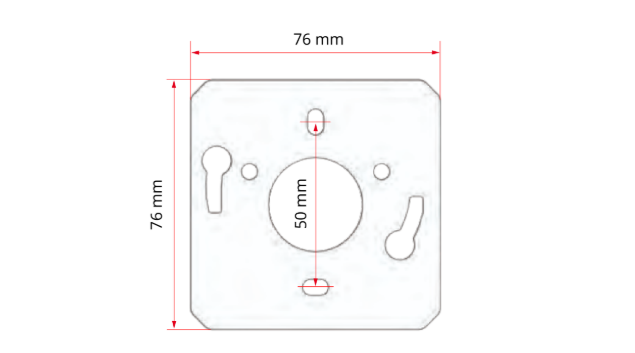
Figure 4: Mounting Plate Mechanical specifications
6. Cleaning and Maintenance protocol#
The ePMDuct is designed for long-term industrial use with minimal maintenance. However, to ensure optimal measurement accuracy, the following procedures are recommended periodically.
6.1 Routine Cleaning#
In high-dust environments (HVAC ducts, industrial workshops), the sampling probe and the internal sensor intake may accumulate particles over time.
- Frequency: Every 6 months.
- Procedure: Disconnect the power supply.
- Warning: Do not use liquids, detergents, or high-pressure industrial compressors, as they may damage the sensitive optical components. Do not blow air directly into the probe by the inlet path.
- Open the ePMDuct Device unscrewing the 4 screws.
- Apply a thin bottle brush to remove dust accumulated on the inox probe sides from the inside towards the outside.
- Use dry, compressed air (canned air) to gently blow out any dust from the inside towards the outside.
6.2 Replacement of the NextPM Advanced Sensor#
The ePMDuct uses a NextPM Advanced sensor module coupled with a brushless pump with a filter in between. This module is a consumable with a typical lifespan of over 10,000 hours in continuous operation (depending on environmental conditions). A replacement kit can be purchased to replace old parts by new ones and continue in duct PM monitoring.
.png)
Figure 5: Maintenance guidance for ePMDuct
When the sensor reaches its end of life (Total Time ON (sec)>36 000 000) or if a “Hardware Error” is reported via Modbus (see Section 4.5 and 4.6), it must be replaced:
- Power Off: Disconnect the 24V DC power supply from the ePMDuct.
- Open the Housing: Unscrew the four cover screws to access the internal components (Blue marks on picture above)
- Sensor Replacement:
- Unplug the sensor’s ribbon cable from the main PCB.
.png)
Figure 6 : ePMDuct inside connections for maintenance
- Unplug the 2 screws (Orange marks Figure 5) to release the device.
- Remove the old NextPM Adv module from its bracket.
- Install the new sensor and reconnect the cable firmly + the 2 fixations screws.
- Filter Replacement:
- Locate the inline filter situated between the NextPM sensor outlet and the pump inlet.
- Disconnect the pneumatic tubing from both sides of the filter.
- Replace with a new filter, ensuring the airflow direction (if marked) is respected.
- Pump Replacement:
- Unplug the pump’s power connector from the PCB.
- Disconnect the tubing and unscrew the pump from its vibration-damping mount (Orange marks).
- Install the new pump, reconnect the tubing (ensure airtight connections), and plug it into the PCB.
- Final Check & Reassembly: Ensure no tubes are kinked or pinched inside the housing
- Close the cover and tighten the 4 screws to ensure the IP seal.
- Verification: Power the unit on. Verify that the pump is running and check the Modbus registers to ensure no “Flow Error” or “Hardware Error” flags are active.
6.3 Flow Rate Testing and Adjustment#
The ePMDuct is factory-set to its nominal flow rate. Over time, or after replacing internal components (pump, filter, or sensor), it may be necessary to verify and recalibrate this flow to ensure measurement consistency.
This adjustment should only be performed by qualified personnel using a calibrated, high-precision mass flow meter. An incorrect flow rate will directly result in inaccurate particle concentration readings.
Procedure for Flow Adjustment:
- Setup: Connect your mass flow meter in series with the ePMDuct sampling probe. Ensure all connections are perfectly airtight.
- Check the flow rate. Nominal flow rate should be between 2.4 and 2.6 L/min.
If not in the range, please follow the procedure below:
- Access the PCB: Open the housing (4 screws with blue marks on picture above) while the device is powered on.
- Stability: Allow the pump to run for at least 20 seconds to stabilize the internal temperature and airflow if needed modify the measuring time to continuous measurements.
- Adjustment
- Locate the flow adjustment potentiometer on the main PCB (refer to the PCB layout in Section 4.4).
- Using a small flat-head screwdriver, gently turn the potentiometer:
- Clockwise: To increase the pump speed and flow rate.
- Counter-clockwise: To decrease the pump speed and flow rate.
- Make small, incremental turns and wait a few seconds for the flow meter to stabilize after each adjustment.
Be careful here, the flowrate at the NextPM Advanced inlet will not be the same as the ePMDuct because of airtightness. Check the flow at the NextPM Advanced inlet before moving the potentiometer, and then slowly turn the potentiometer to increase or decrease the flowrate. Be careful, the sensitivity on potentiometer is high.
- Validation Once the target flow rate is reached and stable, close back the housing, be careful to properly connect the stainless steel probe with the NextPM Adv inlet using the antistatic tubing (see picture below) and tighten the screws to maintain the IP rating. Please check again the flow rate once the device re-assembled.
The target flowrate is between 2.4 and 2.6 L/min.
.png)
Figure 7 : Instruction of connection between Probe and NextPM Advanced inlet during the maintenance ePMDuct closing.